ICP
the measurement of intracranial pressure
The status quo is evolving!
Many brain conditions require the pressure inside the skull to be measured in order to gather important information for diagnostics and to adjust the required treatment effectively to the patient’s needs. The pressure inside the skull is referred to as intracranial pressure (ICP) and is usually measured in mmHG (mmHG - millimetres of mercury).
show more


Cause of fluctuations in ICP
The body has many excellent compensatory mechanisms that keep the ICP at a relatively constant level within a narrow range. However, the position of the patient’s body (lying down/standing up) has a physiological effect on ICP. The pressure (relative to atmospheric pressure) is slightly positive in the supine position, and slightly negative when standing. Actions such as coughing, sneezing and REM (rapid eye movement) sleep can also result in temporary physiological fluctuations in ICP. This is completely normal and healthy.
However, various diseases and injuries, such as traumatic brain injury caused by an accident, strokes, intracranial bleeding, inflammation of the brain or even brain tumours, can result in increased ICP and life-threatening situations.
Elevated ICP levels as well as dizziness, vomiting and impaired consciousness are also frequently observed in patients with hydrocephalus, a condition that causes disruptions to the CSF (cerebrospinal fluid) dynamics, in which either too much fluid builds up in the brain, the intracerebral circulation is disrupted or not enough fluid is resorbed. The most common treatment for patients with hydrocephalus is the implantation of a shunt in order to normalise the pressure in the head by draining CSF e.g. into the abdomen.
To better understand the mechanisms that cause elevated ICP, the Monro-Kellie hypothesis can be used. According to this theory, the total volume of three components, brain tissue, blood and CSF, within the skull must remain the same in order to keep cerebral pressure constant.
Monro-Kellie hypothesis
The total volume within the skull is made up of the three components - brain tissue, blood and CSF. Ideally, they exist in mutual equilibrium and can influence each other if this equilibrium becomes disrupted: if one component increases, another must be displaced from the solid skull where possible. As a result, the increase in volume of one component or the introduction of a new volume (e.g. a brain tumour) can lead to increased cerebral pressure. If the body’s own compensatory mechanisms become exhausted, the ICP can rise above a critical level. This reduces circulation in the brain, which can lead to a lack of oxygen, the death of nerve fibres or even the death of the patient.

Current methods of measuring ICP
Knowing the ICP is important for deciding which treatments to use, such as when treating patients after a stroke, bleeding or a traumatic brain injury. The aim is to use suitable intensive care medical treatments to normalise the elevated ICP in order to prevent complications and subsequent damage. Monitoring the ICP is therefore a key component of neurointensive care.
The most common method of measuring ICP is placing tube-shaped probes into the skull that invasively determine the intracranial pressure. These are connected to an external machine that calculates the pressure and displays the levels. Due to the invasive nature of this procedure, the measurements can only be taken at the patient’s bedside in a hospital ward.
Depending on the location of the pressure-sensitive component in the tube-shaped probe, different types of invasive pressure sensors can be used. If piezoelectric and fibre-optic catheters are used, the pressure is measured right at the tip of the probe that is placed in the skull. Alternatively, the catheter may contain a filler, such as air or fluid as a pressure transmission medium, which transmits the pressure changes at the tip of the catheter to a pressure-sensitive component in an external reader. An example of this is external ventricular drains with an integrated pressure sensor.
Another option is using “telemetric” probes, which are fully implanted and allow the pressure readings to be obtained wirelessly, i.e. using radio waves (non-invasive).
Fully non-invasive sensors that can be attached to the head from the outside do not require implantation. These systems can sense the pressure in the cranial cavity using e.g. an ultrasound. However, the quantitative measurement of ICP cannot currently (in 2020) be achieved with these technologies.
Requirements for stable, reliable ICP sensors
In general medical practice, measurements are usually taken during examinations. These measurements taken at selected points (e.g. using a lumbar puncture) only provide information about a specific moment. As a result, excessively high or low levels and critical trends may not be detected until later on e.g. after clinical symptoms have developed. Furthermore, it cannot be ruled out that the readings may be distorted due to so-called white coat hypertension and the stress of the examination situation.
In neurointensive care, tube-shaped ICP sensors are inserted for a period of one to two weeks and can continuously measure the pressure. This is referred to as time monitoring. Telemetric ICP sensors are an important advancement, particularly for outpatients, who can record the readings continuously throughout the day from home. The parameters and influencing factors that the treating physician derives from these readings can be vital for effectively treating patients.
In production, the sensors are calibrated, during which the readings from the sensor are compared with reference values. The differences are then compensated to correct production-related deviations so that each sensor can calculate the same pressure readings with high precision. It is also useful to eliminate possible temperature dependence of the pressure signal due to calibration.
In order to take reliable, long-term measurements, the pressure sensors must remain stable throughout their service life. When the ICP sensors are implanted, the electronics are exposed to a challenging environment that can greatly impact the long-term functionality. For example, there is the risk of fluid entering the sensor, resulting in corrosion or short circuits that can cause the sensor to fail. Drift of the sensor signal is a common observation, so the measured value no longer equates to the actual value. The sensor’s electronics can be protected from negative influences by hermetic encapsulation, which achieves long-term stability and functionality (Yu, Kim, Meng1, 2014). Metallic housings are an established solution for implantable medical devices due to their very low permeability to gases and liquids (Jiang , Zhou2, 2009). High long-term stability is critical, especially for the monitoring described above.
In order to facilitate the implantation and explantation with minimal trauma to the surrounding tissue, the placed pressure probes must be as small as possible. This is fairly simple for the tube-shaped ICP sensors, as the external reader supplies the energy and processes the readings.
If telemetric pressure probes are used, the technological challenges to be overcome are immense. The placement of the implant entirely within the cranial cavity or subcutaneously and the spatial circumstances there do not allow for the use of batteries with sufficient storage capacity and therefore significant dimensions for operating the sensor. For telemetric sensors, the energy must be transferred from outside to the implant wirelessly via induction. Particularly with higher sampling rates (see below), it is essential when transferring data to maintain a continuous stream of data without disruptions to the communication so that the pressure signal can be recorded in a useable form.
The tube-shaped pressure sensors are inserted transcutaneously (i.e. through the skin and the skull bone) into the cranial cavity. As with all invasive procedures, there is a risk of infection that exponentially increases after just a few days. The movements of the patient can also cause the probe to become dislocated (i.e. shift). This issue can be solved using so-called bolts, in which the pressure probe is secured to the skull with a screw, while also sealing the area through which the implant was inserted from any pathogens entering. To reduce the risk of infection, antimicrobial-impregnated catheters can also be used. However, the challenges above mean that the tube-shaped pressure sensors are only intended for use in hospitals for a few days. The telemetric pressure sensors above are also an alternative approach as these can be read from outside telemetrically and therefore non-invasively.
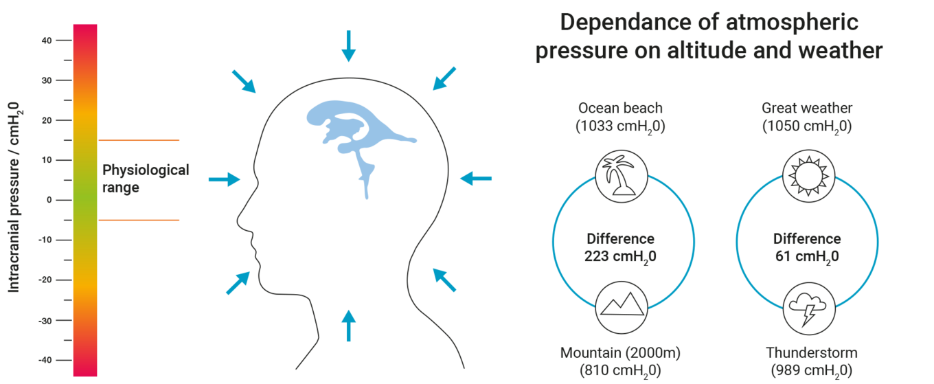
With ICP, it is important to understand that it is given and interpreted as the differential pressure to the ambient pressure (air pressure). It is the difference to the ambient pressure that indicates possible critical cerebral pressure phases and not the actual absolute pressure in the ventricular system. The physiological range of this differential pressure is between approx. -5 and +15 cmH2O. In patients with hydrocephalus, small ICP changes of just a few cmH2O can decide whether a patient experiences symptoms or not. By contrast, the air pressure can fluctuate by more than 50 cmH2O if the weather changes. Height relative to sea level also has a major influence on ambient pressure. When ascending a mountain, the rule of thumb is that for every 1000 m of height, the air pressure drops by around 100 cmH2O.
The figure shows the close physiological window for normal ICP as well as the variance of the ambient pressure depending on the location or weather.
In order to determine the ICP, the pressure measurement systems used must include suitable methods for compensating for the ambient pressure. With tube-shaped sensors, the pressure can be compensated by their design, so the pressure can be measured relative to the ambient pressure straight through the insertion site of the pressure sensor. However, if telemetric pressure sensors are used, two absolute pressure measurements must be taken - the absolute intracranial pressure and the absolute ambient pressure from outside. The two measured pressures are automatically subtracted to calculate the ICP that is required for diagnostics and treatment.
In the past, medical practice focused on measuring average ICP levels, which were used as a basis for selecting suitable treatment to normalise the intracranial pressures. However, current ICP research is looking more and more at analysing the dynamics of the ICP signal. The parameters that can be read from the time-dependent curves, such as amplitudes, can be used to assess compliance and the remaining intracranial compensatory mechanisms of the patient. It is currently assumed that amplitudes greater than 4 mmHG may indicate pathological changes that require therapeutic measures (Schuhmann3, 2008). Amplitude errors would misdirect patient management and are therefore unacceptable from a clinical perspective (Holm4, 2009).
In order to record the rather complex dynamics of intracranial pressure and correctly determine these parameters, the pressure sensors used must have a suitably high sampling rate. The sampling rate defines the number of samples taken per second. If the time-dependent pressure fluctuation is dynamic, the sampling rate must be large enough to properly display the curve.
Nyquist–Shannon sampling theorem
Nyquist–Shannon sampling theorem states that the sampling rate must be at least twice the frequency of the signal to be sampled. The impact of the sampling rate on the presentation of the complex ICP curves that are comprised of various single periodic signals can be shown as follows. At a sampling rate of e.g. 100 Hz (i.e. 100 measurements per second), all of the information from signals ranging between 0 and 50 Hz can be retrieved. Individual signals with higher frequencies cannot be represented. By reducing the sampling rate from 100 to 25 Hz, the individual signals with frequencies of 12.5 to 50 Hz can no longer be determined. Reducing the sampling rate can therefore cause the fine structure of the original complex signals to no longer be adequately represented, resulting in a loss of information (Holm5, 2009).


Sampling rate using sound as an example
Tests on the minimally acceptable sampling rate for intracranial pressure curves show that with measurements under 25 Hz, the curves cannot be realistically recorded and the resulting ampli-tudes are incorrect.

Figure according to Holm et al., Medical Engineering & Physics - data from table 1
With sampling rates from 50 Hz and higher, the curves are represented accurately (Holm6, 2009).
Conclusion
Measuring and monitoring ICP are important tools for deciding the most suitable treatment of various illnesses and trauma for each patient using effective diagnostics. Despite the sometimes high technological requirements of ICP sensors, the treating physician has various systems available to determine the intracranial pressure.
The requirements may vary depending on the case. According to current technology and for the most challenging cases of long-term non-invasive measurements, it can be said that the following requirements are particularly important for high-quality ICP measurement: a high sampling rate of more than 25 Hz, telemetric – i.e. non-invasive – measurement for a low risk of infection, automatic compensation of the ambient pressure, a small structure that transfers high-quality data as well as hermetic encapsulation of the electronics in a metal casing for a high service life and low drift.

ICP is more than a number
Elevated intracranial pressure can cause an inadequate supply to the brain and ischemia as well as the nerves and brain cells to die as a result of the reduced cerebral blood flow. Furthermore, it can cause the dangerous displacement of brain tissue in the skull, e.g. displacement of parts of the cerebellum towards the foramen magnum. This is referred to as herniation.
The aims of treating the patient to reduce elevated intracranial pressure is therefore to restore or maintain the blood supply to the brain and prevent the displacement of brain tissue. Treatment should also improve the well-being of the patient and reduce or, ideally, relieve symptoms, such as headaches and nausea.
In the past, treatment focused on lowering the ICP to below a defined limit. The diagnostic basis for this is invasive pressure sensors, which are used to determine the intracranial pressure e.g. in neurointensive care units. These devices display the measured mean ICP.
However, the past few years in particular have shown that looking solely at an ICP limit is not enough to effectively treat patients (Carrera, Kim, Castellani, 20107). There are many reasons for this: Reducing the ICP to a single figure results in the loss of a lot of valuable information about the cerebrospinal regulation processes. Such limits overly simplify the very complex and heterogeneous pathologies (Le Roux, 20168). Limit values are also typically calculated in studies with a large number of participants, so the focus is not on the individual patient. Such limit values generally only allow the treating physician to react if the given intracranial pressure has been exceeded (Le Roux, 20169).
To further explain this, below is an example comparison of two patients whose intracranial pressure is above the physiological, i.e. healthy, range at the time the measurement was taken: Patient A has high compliance (Le Roux, 201610) , i.e. small changes to the intracranial conditions do not cause a significant change in ICP. The elevated pressure readings may be well tolerated by this patient. On the other hand, patient B shows reduced compliance. Small pathological increases in volume lead to a significantly elevated ICP and critical reactions in this patient. Both patients must be treated differently for the increase in ICP, focusing on an ICP limit is not sufficient in these cases. Other parameters, such as compliance, must be taken into account when treating each patient and when considering different treatment options. But how can these parameters be determined?
Advances in measurement technology and data processing have now made it possible to evaluate larger data sets in real-time (e.g. while the measurements are being taken). This provides the treating physician with new information that would not have been accessible in the past without the support from technology. As a result, analysing the time of the ICP curves is becoming more and more prevalent in the field of intracranial pressure sensors. It could be shown that the dynamics of ICP, its waveform and the resulting parameters provide useful information that increases the quality of the patient’s treatment and proactively counteracts critical trends (Le Roux, 201611) (Czosnyka, Smielewski, 200712).
Compliance
Below is a detailed explanation of the term compliance used above. To give a clearer description, compliance reflects something like the “softness” or “elasticity” of the entire contents of the cranial and spinal cavities. This is not only typical in the brain, but also affects the entire central nervous system (CNS), i.e. the cranial and spinal cavities. This elasticity is a type of “pseudo-elasticity”, due to the fact that the elements contained in the cranial/spinal cavity, such as blood and CSF, are inherently incompressible, or, in other words, rigid. Compliance comes about due to the fact that with every new “volume”, e.g. a build-up of excess CSF (hydrocephalus), a bleed (haematoma) or a growth (cancer, cysts or swelling), venal blood is essentially displaced from the rigid space and forced out into the body. Therefore, if compliance is normal, such masses will only cause a slight increase in intracranial pressure to begin with, which is why they are often associated with a so-called "pressure reserve capacity”. If the mass becomes too large, this reserve capacity quickly gets used up and the ICP increases sharply. However, masses that are too large are not the only reason for reduced compliance. In fact, this can also be caused by a pathological hardening of the tissue and blood vessels, particularly the veins (sclerosis). Measuring compliance has “diagnostic value”, as it makes it possible to find out some information regarding the extent of the mass, as well as the state of the tissue and blood vessels.
The precise medical definition of compliance in the form of a pressure to volume ratio (C = dV/dP) is set out in the following ICP volume curve:

This means compliance corresponds to the inverse increase at a specific point of the patient’s ICP volume curve.
Although only a small percentage of the total CSF is contained in the bony spinal canal, this means it contains a greater amount of venal blood. The dural sac, which contains the spinal CSF, is flexible and expands significantly when the person stands, due to the CSF sinking down from the skull. The spinal canal probably accounts for more than 50% of total compliance.
Intracranial pressure curves - a crash course
The ICP waveform can have three main components (Czosnyka, Smielewski, 200713):
- Pulse waveform, associated with the heartbeat (typical heart rate 50-180 bpm)
- Respiratory waveform, associated with breathing (typical respiratory rate of 8-20 cycles/minute)
- Slow vasogenic waveform, i.e. from the blood vessels
for example so-called Lundberg A and B waves can be observed in the pressure signal (typically 0.3-3 cycles/minute)(Czosnyka, Smielewski, 200714)
An ICP curve over time produces the following example image (modified according to Czosnyka, Smielewski, 200715):

The pulse (1) and respiratory (2) waveforms show significantly smaller pressure changes compared to the vasogenic (3) Lundberg A and B waves.
Pulse waveform
The diagnostic value of pulse amplitudes
So-called pulse amplitudes (AMP) are determined in diagnostics as a quantitative measure of the intensity of the pressure pulses. These refer to the pressure difference between the maximum and the two adjacent minima of each pulse. The pulse amplitudes are also referred to as the mean ICP wave amplitude (MWA) in the literature.

The pulse amplitudes (AMP) depend on the physiological and pathological conditions in the cranial and spinal cavity. The correlations can be described using the ICP volume curve.
In the event of high compliance (on the left-hand side of the curve with a slight rise in the ICP volume curve), the pulsating volume changes lead to negligible pressure pulses, the related pulse amplitudes are small. If compliance is reduced (e.g. in patients with tumours), large pulse amplitudes can be observed. Compliance therefore reflects something like the “reserve capacity” of the brain and gives information on the extent to which addition intracranial volumes can cause the ICP to significantly rise immediately or whether displacing blood and CSF from the cranial cavity can compensate for this effect. If ICP values are very high, the curve flattens.
Figure according to (Czosnyka, Pickard, 200416)

Figure according to (TeachMeSurgery, 202017)
This correlation allows information about compliance to be obtained by quantifying the pulse amplitudes. It is known that, for example, amplitudes greater than 4 mmHG can indicate pathological changes with reduced compliance (Eide, 201618).
The pulse amplitudes can be measured straight from the ICP curve. The readings depend on possible drift effects of the pressure sensors.
In order to determine the pulse amplitudes, the measurement system must have a sufficiently high sampling rate in order to be able to precisely determine these values. Good software is also required that can objectively and automatically analyse the ICP waveforms (Pennacchietti, 202019).
The diagnostic value of the correlation coefficient RAP
– or in simple terms:
The detailed analysis of the ICP volume curve shows a distinct exponential rise. When the intracranial pressure reaches a certain level, a turning point in the curve is observed where the graph flattens out as the ICP increases. Thus, the pulse amplitudes rise as the ICP increases up to the turning point when they drop again. Therefore, small pulse amplitudes on the left (high compliance with low ICP) as well as on the right (low compliance with high ICP) can be observed from the turning point. When considered together, the ICP and pulse amplitudes therefore do not clearly describe the part of the ICP volume curve in which the patient’s intracranial state is.
In order to make a clear statement on compliance and the compensatory reserve for each patient, another parameter - the RAP index - was introduced in addition to the above parameters. The RAP index describes the statistical correlation between the mean ICP and AMP. R in the term RAP stands for the correlation coefficient, A is the abbreviation for amplitude and P is the mean pressure. The value of the RAP index can be from -1 to +1 (Czosnyka , Smielewski, Timofeev, 200720).
What general statements can be made with a correlation coefficient? The correlation coefficient generally describes the dependency of variable A on variable B:
Example 1: The values of variable A increase while the values of variable B increase linearly. In this case, the correlation coefficient of both variables is +1, which is referred to as a positive linear relationship.
Example 2: The values of variable A increase while the values of variable B decrease linearly. The correlation coefficient takes the value of -1, in this case, a negative linear relationship exists between the two variables.
A correlation coefficient of 0 indicates no correlation, i.e. changes to variable A do not result in changes to variable B. Values between 0 and 1 or 0 and -1 indicate a correlation between both variables that is not fully linear (Ratner, 200921).
If this is applied to the RAP index, the following statements can be made: When intracranial pressure readings are small, small volume changes on the left part of the ICP volume curve do not cause the pulse amplitudes to increase. Since there is no correlation between these two values, the RAP index is 0.

When the intracranial pressure readings are higher, the RAP index takes the value of >0 around the steep rise of the ICP volume curve, which means the rise in ICP leads to an increase in the pulse amplitudes. The compensatory reserve is low in this range, so small volume changes lead to a sharp increase in ICP. If the ICP further increases, the pulse amplitude drops again from the turning point of the ICP volume curve. Here, the RAP index is <0. At the turning point, the RAP therefore changes sign. This identifies a critical range from which elevated ICP values can lead to ischemia, irreversible brain damage and herniation (Jin, Choi, Kim,201922). Ultimately, pulsations are no longer observed in the pressure signal when the pressure readings are very high, the RAP index once again takes the value of 0.
From a practical perspective, the RAP index is relevant e.g. in neurointensive medicine. In most patients who are admitted to hospital with traumatic brain injuries, a good compensatory reserve is observed within the first few hours (RAP is 0), however this deteriorates when cerebral oedema occurs. The RAP then consistently shows values close to +1 (Czosnyka, Smielewski, Timofeev, et al., 200723).
On the one hand, a reduction or increase in the RAP index may be due to the change in position of the patient’s craniospinal system on the ICP volume curve. On the other hand, pathological effects may also lead to a change in the shape of this curve over time and a different RAP index being calculated.
In summary, it can be stated that the RAP index has proven to be a reliable measure for the compensatory reserve (Czosnyka, Steiner, Balestreri, et al., 200524) and compliance (Varsos, Kasprowicz, Smielewski, Czosnyka, 201425).
In order to determine the RAP index, the pressure measurement system must have low drift and high precision as well as a suitable sampling rate of the pressure signal in order to calculate the RAP based on the calculated mean ICP and pulse amplitudes.
The diagnostic value of the fine structure of the pressure pulses
A detailed analysis of the curve of the pulsatile wave over time reveals a characteristic fine structure. It shows that every pressure pulse is comprised of at least three single pulses. These are identified on the time axis from left to right with P1, P2 and P3. Where do they come from and can they be used for a diagnosis?
The P1 wave, also referred to as the “percussion wave”, is the result of the arterial pulse that spreads to the cranial cavity. P1 is the result of the direct expansion of the arterial walls due to the pulse (so-called windkessel effect) that is transferred to CSF and other intracranial components and can therefore be identified in the pressure signal (Czosnyka, Czosnyka, 202026).
By comparing the time curves of the arterial blood pressure and the ICP, other components in the intracranial pressure signal can be identified. P3, also referred to as the “dicrotic wave”, is likely to originate from the veins.

Figure according to (March, Hickey, 201627) and (Czosnyka, Czosnyka, 202028)
For P2, however, no direct association to a part of the arterial pressure curve could be found. Examinations show that P2 may be linked to the pulsatile arterial intracranial blood volume (Czosnyka, Czosnyka, 202029). These pulsatile increases in volume cause pulsatile pressure changes in the skull as a response (see chapter “The diagnostic value of pulse amplitudes”). The amplitude of P2 therefore depends on the elastic properties of the cranial cavity and therefore on compliance.

Figure according to (Stettin, 200830)
If compliance is high, the arterial pulse will be cushioned by the cranial cavity, the intensity of the pulse is P1 > P2 > P3 (see point (1) in the curve). With high compliance, the cranial cavity acts like a sponge that absorbs the pulses. If intracranial compliance is reduced, intracranial components cause the pulse to be transferred more strongly, which leads to an increase in the intensity of P2 so that the intensities shift: P1< P2 > P3 (see points (2) and (3) in the curve). In this case, the elastic properties of the cranial cavity act like a stone with low compliance. The fine structure of the individual pressure pulses is therefore dependent on compliance.
In summary, in addition to the pulse amplitudes AMP, the fine structure of the individual pressure pulses also contains diagnostic information about compliance.
In order to determine the fine structure, the pressure measurement system used must have a sufficiently high sampling rate in order to be able to determine the intensities of the three components in the individual pressure pulses.
Respiratory waveform
In addition to the pulsatile waveform, morphologies can also be observed in the ICP curve that originate from respiration. This is due to the following effects: During inhalation, the intrathoracic pressure drops, which causes the cerebral venous pressure to reduce. The outflow of the blood increases and the ICP drops. The opposite effect when exhaling causes a sinusoidal pattern in the ICP curve in line with the respiratory rate. An increase of the intrathoracic pressure and therefore the increase of the ICP can also be observed during the Valsalva manoeuvre (e.g. during bowel movements) and when coughing, sneezing and vomiting (Peate, Wild, Nair, 201831).
Example from clinical practice
As described above, pulsatile and respiratory components can overlap in intracranial pressure curves as follows:

Important parameters can be derived from the ICP curves over time and the mean ICP (here approx. 5 mmHg) can be determined. The mean is shown in the figure in blue. The peaks of the pulsatile component show a gap of approx. 0.7 seconds (purple marking), i.e. the associated contraction of the heart has a frequency of 85/min. The pulse amplitude of the pulsatile component is high in the example at approx. 5 mmHg, which may indicate reduced compliance (red marking).
The peaks of the respiratory component show a gap of approx. 7 seconds, i.e. the breathing rate is approx. 9 breaths/minutes (green marking). The observed amplitudes of the respiratory component are significantly smaller than the amplitudes of the pulsatile component in the example shown.
Slow vasogenic waveform
When measuring the ICP, slower changes to the ICP signal can also be observed in addition to high frequent pulsatile and respiratory components. These are morphologies of vasogenic (from the blood vessels) origin.
According to Lundberg, three waveforms A, B and C can be identified (Lundberg, 196032). The most important characteristics of Lundberg A and B waves are described below. Explanations of the Lundberg C waves will be omitted due to their unclear clinical relevance.
Lundberg A waves
Lundberg A waves are also referred to as plateau waves. They have the following shape: Starting with a certain ICP, the ICP increases sharply, followed by a plateau lasting for 5 to 20 minutes and pressures over 50 mmHg are reached. After this time, the pressure readings drop dramatically.

Lundberg A waves are caused by the following effects: The ICP readings that are typically high to begin with cause a reduction in the cerebral perfusion pressure (CPP). This is a measure of circulation in the brain. The CPP is the difference between the mean arterial pressure (MAP) and the ICP.

If the cerebral perfusion pressure is no longer enough to meet the metabolic needs in the cranial cavity, this causes cerebral artery vasodilation, i.e. expansion of the blood vessels as part of so-called autoregulation. This increases the cerebral blood volume, which, in turn, causes an even higher ICP. The repeated cycle causes life-threatening ICP readings. Lundberg A waves are pathological and must be treated immediately.
Lundberg B waves
The description of Lundberg B waves is very inconsistent in the literature, various waveforms are described using this term (Martinez-Tejada, Arum, Wilhjelm, Juhler, Andresen, 201933). For example, there are reports that Lundberg B waves can be both sinusoidal and ramp-shaped, with the individual wave crests occurring at a frequency of 0.5 to 3/min.


It is described that these waves could indicate reduced compliance (Spiegelberg, Preuß, Kurtcuoglu, 201634). However, there is currently no consensus in the literature about the value of Lundberg B waves in diagnosing hydrocephalus and predicting whether a patient can benefit from a shunt.
The ramp-shaped Lundberg B waves appear to be linked to elevated pCO2 readings (i.e. an increase in the concentration of CO2 in the arterial blood) caused by snoring and sleep apnoea (Spiegelberg, Preuß, Kurtcuoglu, 201635 and Román, Jackson, Fung, et al., 201936). On the other hand, sinusoidal Lundberg B waves may be related to changes in the arterial blood pressure, which are not associated with the breathing rhythm or arterial CO2 (Spiegelberg, Preuß, Kurtcuoglu 201637).
In summary, various morphologies can occur in the curve of ICP readings. For example, the pulsatile and respiratory waves are physiological i.e. they also occur in healthy people. By contrast, the Lundberg A waves clearly indicate pathological changes and must be treated immediately due to the life-threatening high ICP readings.
Summary
Bibliography
Chapter 1:
1: Lawrence Yu, Brian J Kim, Ellis Meng; Chronically implanted pressure sensors: challenges and state of the field; Sensors, 2014 Oct 31;14(11):20620-44.
2: Jiang G., Zhou D.D. (2009) Technology Advances and Challenges in Hermetic Packaging for Implantable Medical Devices. In: Zhou D., Greenbaum E. (eds) Implantable Neural Prostheses 2. Biological and Medical Physics, Biomedical Engineering. Springer, New York, NY
3: Schuhmann et al., Pediatr. Neurosurg., 2008, 44, 269-279
4,5,6: Holm et al., Medical Engineering & Physics 31 (2009) 601–606
------------------
Chapter 2:
7: Carrera E, Kim DJ, Castellani G, et al. What shapes pulse amplitude of intracranial pressure?. J Neurotrauma. 2010;27(2):317-324. doi:10.1089/neu.2009.0951
8,9,10,11: Le Roux P. Intracranial Pressure Monitoring and Management. In: Laskowitz D, Grant G, eds. Translational Research in Traumatic Brain Injury. Boca Raton (FL): CRC Press/Taylor and Francis Group; 2016.
12, 13,14, 15: Czosnyka M, Smielewski P, Timofeev I, et al. Intracranial pressure: more than a number. Neurosurg Focus. 2007;22(5):E10. Published 2007 May 15. doi:10.3171/foc.2007.22.5.11
16: Czosnyka M, Pickard JD. Monitoring and interpretation of intracranial pressure. J Neurol Neurosurg Psychiatry. 2004;75(6):813-821. doi:10.1136/jnnp.2003.033126
17: TeachMeSurgery, 2020: teachmesurgery.com/neurosurgery/flow-and-pressure/monro-kellie-doctrine/ abgerufen am 7. September 2020
18: Eide PK. The correlation between pulsatile intracranial pressure and indices of intracranial pressure-volume reserve capacity: results from ventricular infusion testing. J Neurosurg. 2016;125(6):1493-1503. doi:10.3171/2015.11.JNS151529.
19: Pennacchietti, Valentina et al. “Single center experiences with telemetric intracranial pressure measurements in patients with CSF circulation disturbances.” Acta Neurochirurgica (2020): 1 - 11.
20: Czosnyka M, Smielewski P, Timofeev I, et al. Intracranial pressure: more than a number. Neurosurg Focus. 2007;22(5):E10. Published 2007 May 15. doi:10.3171/foc.2007.22.5.11
21: Ratner, B. The correlation coefficient: Its values range between +1/−1, or do they?. J Target Meas Anal Mark 17, 139–142 (2009). doi.org/10.1057/jt.2009.5
22: Jin SC, Choi BS, Kim JS. The RAP Index during Intracranial Pressure Monitoring as a Clinical Guiding for Surgically Treated Aneurysmal Subarachnoid Hemorrhage: Consecutive Series of Single Surgeon. Acute Crit Care. 2019;34(1):71-78. doi:10.4266/acc.2019.00437
23: Czosnyka M, Smielewski P, Timofeev I, et al. Intracranial pressure: more than a number. Neurosurg Focus. 2007;22(5):E10. Published 2007 May 15. doi:10.3171/foc.2007.22.5.11
24: Czosnyka M, Steiner L, Balestreri M, et al. Concept of "true ICP" in monitoring and prognostication in head trauma. Acta Neurochir Suppl. 2005;95:341-344. doi:10.1007/3-211-32318-x_70
25: Varsos GV, Kasprowicz M, Smielewski P, Czosnyka M. Model-based indices describing cerebrovascular dynamics. Neurocrit Care. 2014;20(1):142-157. doi:10.1007/s12028-013-9868-4
26: Czosnyka M, Czosnyka Z. Origin of intracranial pressure pulse waveform. Acta Neurochir (Wien). 2020;162(8):1815-1817. doi:10.1007/s00701-020-04424-4
27: nursekey.com/intracranial-hypertension-theory-and-management-of-increased-intracranial-pressure/ abgerufen am 07. September 2020
28, 29: Czosnyka M, Czosnyka Z. Origin of intracranial pressure pulse waveform. Acta Neurochir (Wien). 2020;162(8):1815-1817. doi:10.1007/s00701-020-04424-4
30: d-nb.info/1001032489/34 abgerufen am 7. September 2020
31: Ian Peate, Karen Wild, Muralitharan Nair: Nursing practice: knowledge and care, edited, 2018, Wiley
32: Lundberg N. Continuous recording and control of ventricular fluid pressure in neurosurgical practice. Acta Psychiatr Scand Suppl. 1960;36(149):1-193.
33: Martinez-Tejada I, Arum A, Wilhjelm JE, Juhler M, Andresen M. B waves: a systematic review of terminology, characteristics, and analysis methods. Fluids Barriers CNS. 2019;16(1):33. Published 2019 Oct 15. doi:10.1186/s12987-019-0153-6
34, 35: Andreas Spiegelberg, Matthias Preuß, Vartan Kurtcuoglu,B-waves revisited, Interdisciplinary Neurosurgery, Volume 6, 2016, Pages 13-17, doi.org/10.1016/j.inat.2016.03.004.
36: Román, G.C., Jackson, R.E., Fung, S.H. et al. Sleep-Disordered Breathing and Idiopathic Normal-Pressure Hydrocephalus: Recent Pathophysiological Advances. Curr Neurol Neurosci Rep 19, 39 (2019). doi.org/10.1007/s11910-019-0952-9
37: Andreas Spiegelberg, Matthias Preuß, Vartan Kurtcuoglu,B-waves revisited, Interdisciplinary Neurosurgery, Volume 6, 2016, Pages 13-17, doi.org/10.1016/j.inat.2016.03.004.